


Discover
The electrical mass
Find out what the electrical mass is, its legislation and its specificities.
Electrical symbols for mass and earth
In legal terms, according to the decree N° 88-1056 of November 14, 1988, mass is :
"The conductive part of an electrical equipment that can be touched by a person, which is not normally under voltage but can become so in the event of an insulation fault of the active parts of this equipment".
It is therefore a conductive part of a circuit, of a set of circuits, or of a structure or a set of metallic structures, whose electrical potential must be zero. That is to say that an electric voltage can be measured from this conductive part.
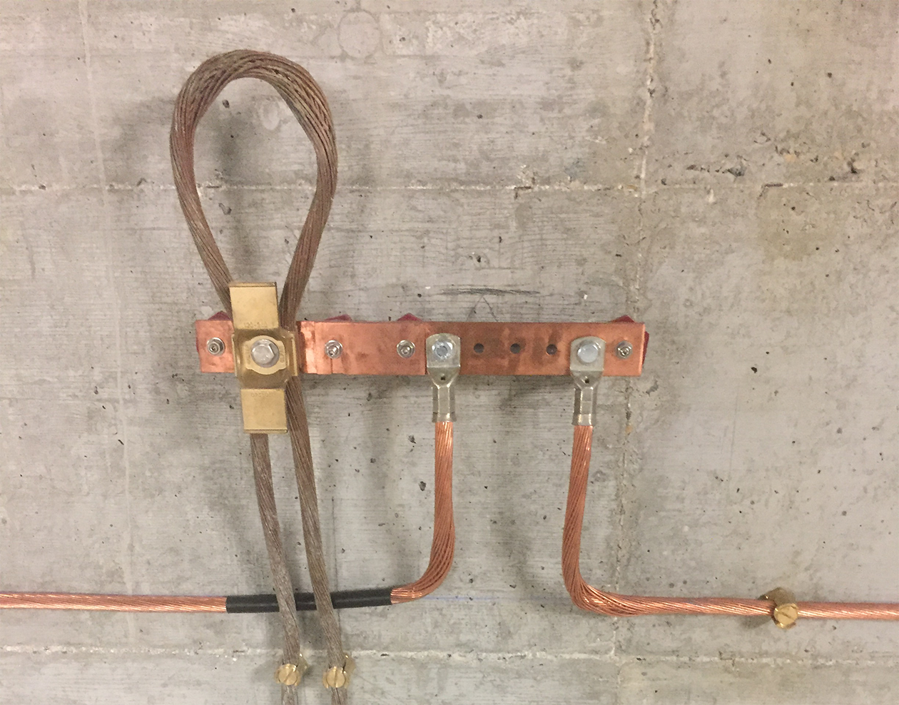
Therefore, the grounding allows equipotentiality between the various devices and metal structures inside a building or a vehicle. That is to say that each device and each metal frame is connected to the other devices and frames, and that -through this connection- all are brought to the same reference voltage. In order for this voltage to remain zero, even in the event of an electrical fault in one of the devices, all of these interconnected masses must be connected to earth.
The grounding then allows to cancel or at least to reduce the risks of electric discharges in industrial, domestic and other installations (as for example on board of vehicles). Each room of a building must be equipped with grounding connections, where should also be connected the water pipes, the gutters, the metal frames, the reinforcement of concrete constructions, etc. All these metallic masses must be connected to each other, to form an electrical mass, which must be connected to an earth connection.
However, the ground connection is not always possible, especially on board some vehicles: On a boat, the hull is simply in contact with the water, which brings it to a zero potential. On board a car, a truck or a two-wheeler, there is no grounding. This is why you can feel a discharge of electricity when you get in or out of the car. However, this can be remedied by using an antistatic wire or grounding strip to connect the vehicle chassis to the ground and bring it to zero potential. Rail vehicles are permanently connected to the ground through contact with the rail. Finally, the grounding is obviously impossible on board an aircraft, but the cabin is connected to the ground before boarding or disembarking, to bring it to zero potential. The same procedure must be followed before filling a tanker truck, to avoid any flashover or explosion.
To understand the difference between ground and earth, it is important to understand that the ground connection allows equipotentiality, i.e. the connection of several devices, circuits and metallic structures to the same potential, whereas the earth connection allows this potential to be maintained at zero volts. The ground is therefore a technical necessity, while the earth is a safety requirement.
Symboles électriques de la masse et de la terre
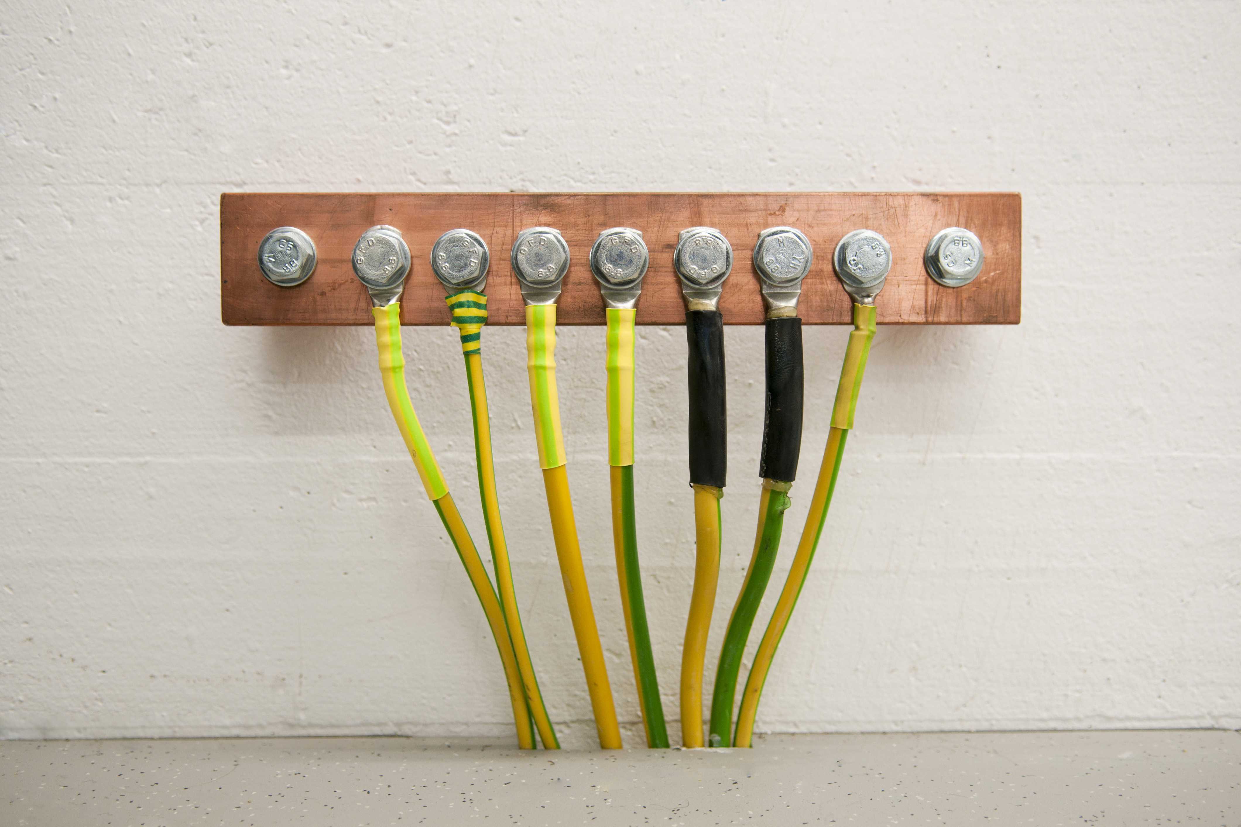
According to the electrical standards, whether in building electricity, household appliances, electronics or industrial electricity, green and yellow wire is used for the connection to the ground, as for the earth connection. However, unsheathed wire or bare metal braid can also be used, since these passages should not normally carry electrical charges, or if they do, allow their direct dissipation to the ground.
This is the very purpose of grounding and bonding circuits: electricity always chooses the most direct and least resistive path to the ground. This is why, in the event of an electrical fault in an appliance, you can touch it without feeling a discharge - and therefore without danger - if it is well connected to the ground.
How to ground a device
In an electrical circuit supplied with direct current, one of the two supply wires is always connected to the metal frame of the device, i.e. to the ground: by convention, it is invariably the negative, while the positive is isolated. Electronic equipment made up of several interdependent circuits requires this ground as a potential reference in order to function correctly.
In alternating current, the phase and the neutral are both isolated, and therefore not connected to the ground. Only the chassis of the device is connected to the earth of the mains socket.
Examples of applications
Filtering of unwanted signals
A specific case of the usefulness of the electrical ground -always provided that it is connected to the ground- is the filtering of sinusoidal signals by a filter called "low-pass". This filter blocks undesirable high frequencies by short-circuiting them to ground, while letting through the low frequencies that we want to keep (hence its name). This very simple circuit consists of a resistor R placed in series in a circuit, then a capacitor C placed in derivation. The calculation of this filter is given by the formula :
fc = 1/ 2 ¶ RC
fc is the cut-off frequency, expressed in Hertz. The value of the resistance R is given in Ohms, and that of the capacitor C in Farad. We will round 2 ¶ to 6.28.
This type of filter can be used to remove a high-pitched whistle in an audio circuit, or to eliminate harmonic frequencies in a power supply circuit. There are other different cells, which can be used to suppress low frequencies (high-pass filter), or to suppress both high and low frequencies (band-pass filter), or to filter certain defined frequencies, while letting through some others, lower and also higher (rejecting filter).
In all cases, the unwanted frequencies must be evacuated to ground, which requires a prior connection to ground. Otherwise, these unwanted signals would stagnate in the circuit, which would imply the inefficiency of the filtering, or even a danger in certain cases.
The connection to the ground and to the earth, if they are not really part of the filtering cells, are an obligatory complement for their correct operation.
Elimination of radiation, interference currents and high frequencies through the ground shielding
Ground shielding is a grounded metal enclosure that surrounds certain electronic circuits, either to protect them from interfering radiation or to prevent these circuits from emitting interfering signals themselves. To be effective, the ground shield must be connected to an electrical ground network, which is itself connected to the earth.
Some electrical or electronic equipment can, by its very nature, generate unwanted signals that are disruptive to other equipment in the vicinity.
A well-known example is the radiation produced by high-voltage power lines and the transformers associated with these lines. Passing near them can be perceived by a radio and interfere with the reception of certain frequencies. In theory, a ground shield would eliminate these disturbances by sending them to the ground. In practice, it is obviously not possible to isolate these lines which are in the open air. This problem has been overcome by the widespread use of higher radio frequencies - the so-called FM band - which are less sensitive to this radiation, to the detriment of lower frequency bands, known as longwave and shortwave, which are now less and less used.
However, spurious emissions still exist, although they are no longer perceived. We have simply bypassed the problem.
Similar disturbances are also produced by the so-called "switch-mode" electronic power supplies (electronic regulation by switching, used for their high efficiency) such as those used in microcomputers, but whose use has also become widespread in consumer electronics in recent decades. At the beginning of the use of switch mode power supplies, there were many problems due to interference radiation. Since then, progress has been made in filtering these circuits (see low-pass filters, previous paragraph) and shielding, ground connections and earthing have become widespread.
To avoid or limit the problems of parasitic radiation, some installations are placed in rooms that are particularly well connected to ground and earth, or even in confined metal enclosures that form a ground network that is virtually hermetic to external signals and radiation. The effect of a Faraday cage is thus obtained.
This is particularly the case in computer rooms and web servers, radio and television transmitters, transformers of the EDF network or industrial installations, etc.
Electrical measurement laboratories do not create interference, but are sensitive to external disturbances. Therefore, they are also protected by the same shielding process.
Optimal ground connections and electrical shielding are achieved by means of ground straps or ground braid. Because of this proven effectiveness, metal braid shielding is used in all cables that carry weak signals and are sensitive to electrical interference. For example, television antenna cables, which carry weak signals at high frequencies, consist of a central core where the high frequency signals pass through, surrounded by a concentric braided shield made of copper or tinned copper.
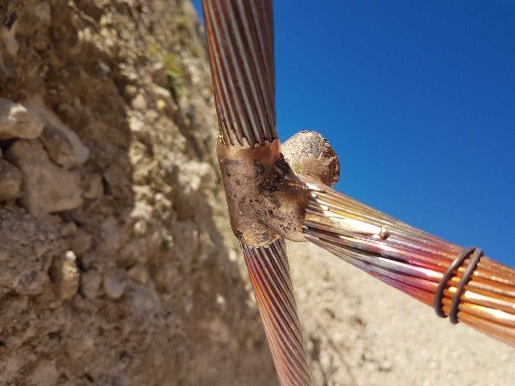
Ground and earth circuits for lightning protection
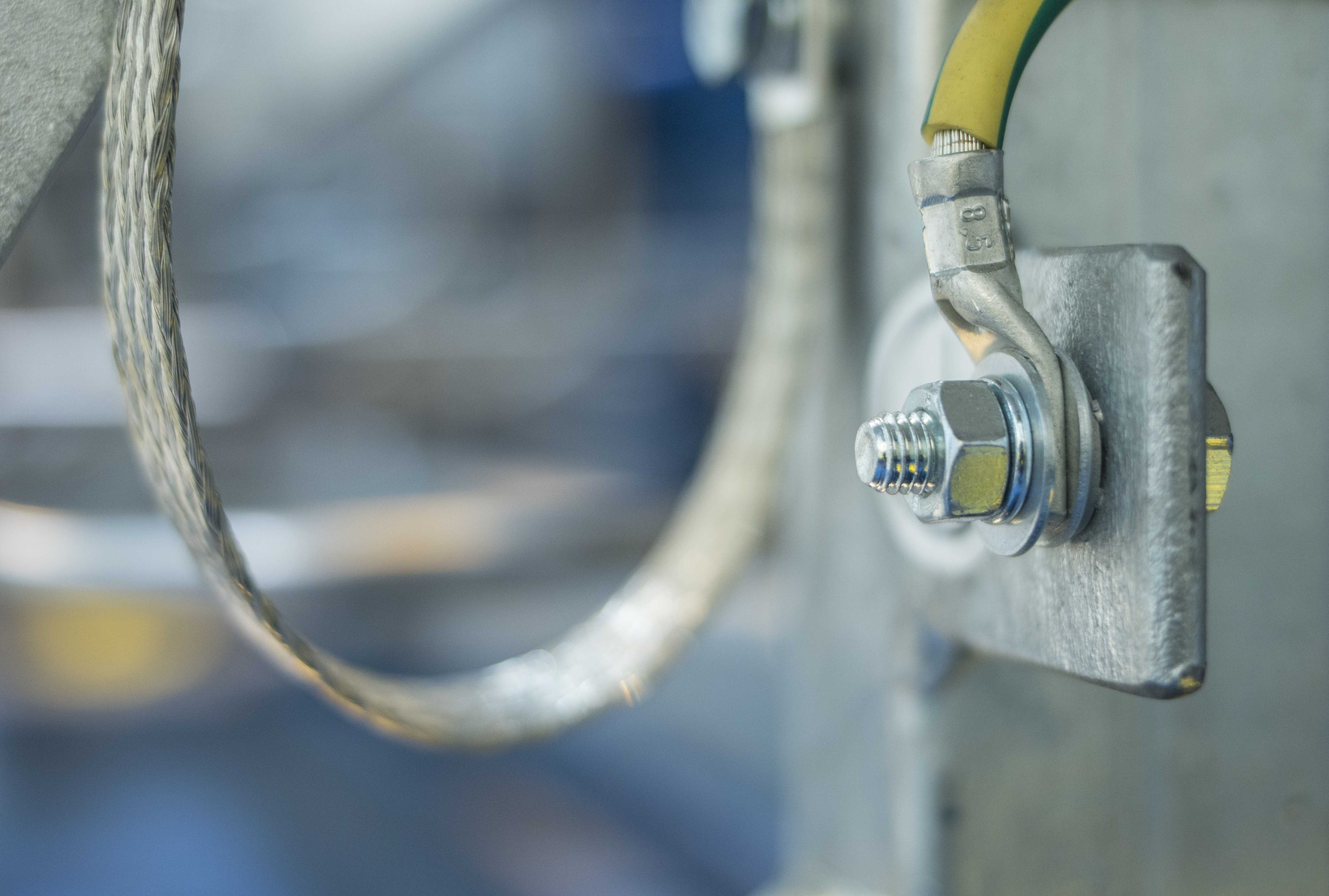
This connection could be made by electrical cable, but most often we use ground braid. The braid has the advantage of being more flexible, and it is better suited to mechanical bending or twisting. For example, the flat braid allows to connect in an optimal way two perpendicular surfaces of an electrical box or the metal frame of a motor to another conductive structure (rail or electrical gutter), and more generally planes out of alignment.
To be efficient, a ground connection must be as short as possible, and have a maximum contact surface: Because of its flat shape, the ground braid is the most suitable conductor for this purpose.
Furthermore, the braid has a much lower impedance than a wire or cable made of the same material, especially at high frequencies. This implies a lower resistance, and therefore a better electrical contact. The impedance of strip is even lower, but strip is much stiffer and does not offer the flexibility of braid.
How do you ground devices, circuits and metal housings?
This connection could be made by electrical cable, but most often we use ground braid. The braid has the advantage of being more flexible, and it is better suited to mechanical bending or twisting. For example, the flat braid allows to connect in an optimal way two perpendicular surfaces of an electrical box or the metal frame of a motor to another conductive structure (rail or electrical gutter), and more generally planes out of alignment.
To be efficient, a ground connection must be as short as possible, and have a maximum contact surface: Because of its flat shape, the ground braid is the most suitable conductor for this purpose.
Furthermore, the braid has a much lower impedance than a wire or cable made of the same material, especially at high frequencies. This implies a lower resistance, and therefore a better electrical contact. The impedance of the strap is even lower, but it is much stiffer and does not offer the flexibility of the braid.
Therefore, braid is the preferred conductor for ground connections.
The grounding braid exists in standard dimensions or can be made to measure, in different widths, lengths, and thicknesses, depending on the dimensions of the structures that it must connect, and the voltages and intensities that it allows to convey. We also talk about the short circuit current to earth, on which depends the dimensioning of the braid. It is variable according to whether the braid is used to connect the least of a car battery to the ground, for use on an industrial or domestic installation, or for protection against lightning.
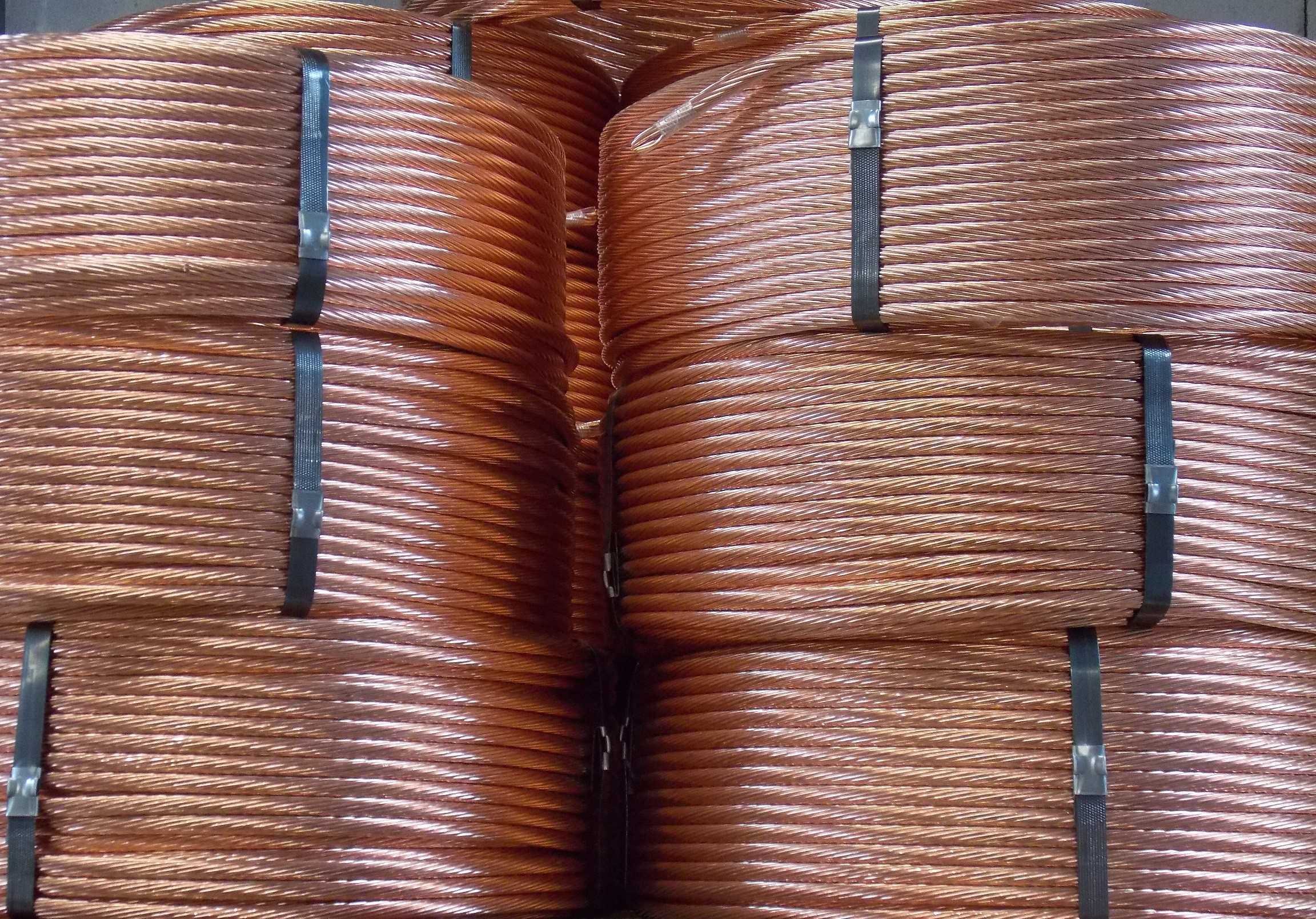
The material used for the grounding braid is generally copper, for its good conductivity, and for its malleability.
To avoid oxidation, copper braid can be tinned. There are also aluminum braids. This material is less conductive and mechanically less flexible than copper, but it has the advantage of being less alterable. Aluminum braid is less commonly used.
The braid is fastened by means of crimped holes, into which connecting screws are inserted. The length of the braid is generally defined by the distance between the two holes. The diameter of the holes is proportional to the dimensions of the braid and defines the size of the screws to be used.
The shape of the braid can be flat or round.
Depending on its use, the mechanical characteristics of the braid are :
- The type, round or flat braid
- Dimensions: length, width, thickness
- The section
- The length between axes
- The diameter of the holes
- The material: copper, tinned or not
MALTEP offers braids for all ground and earth connections, in standard sizes, but also in custom sizes, with cross-sections ranging from 6 mm² to 240 mm², or more.