Earthing

How to realize a proper earthing?

Find out how to safely earth your facilities

What is earthing?

Presentation

The grounding is a connection between the earth (called here "grounding" at 0 volt potential) and metal casings of electrical appliances that are faulty. This connection is made with a conducting wire. The electrical insulation fault is then closed; the electrical installation is therefore no longer dangerous for humans.

The electrical appliance can also be switched off by means of a differential circuit breaker: this device automatically cuts off the power supply in the event of leakage current; the latter then passes immediately into the earth. Electric shocks are thus avoided.

Earthing is therefore a matter of safety first and foremost (home, professional premises...) and helps avoid any risk of electrocution. It also allows to protect electrical appliances (washing machine, dishwasher for example) to avoid that they are damaged too quickly.

The earth is connected to the armature of light points, sockets and boxes of class 1 electrical appliances only.

Electrical protection classes:

  • Class 0: a device with functional insulation without an earth connection (the sale of this type of device is forbidden in Europe).
  • Class 1: a functionally insulated device with an earth connection and an equipotential bonding.
  • Class 2: device with reinforced insulation without accessible metal parts.
  • Class 3: device operating at very low safety voltage (requires a safety transformer allowing galvanic isolation of two circuits).

All commonly used equipment, regardless of class, must have at least two means of protection against electric shock. The primary protection protects against electric shock but its failure should not be neglected. The secondary protection protects against electrocution if the primary protection fails.

It is possible to measure the earth, using an ohmmeter. It is a device for measuring electrical resistance (expressed in ohms) provided with two electrodes. These connect the ohmmeter to the earth. According to Ohm's law, the resistance R (in ohms) is equal to the ratio of the voltage U (in volts) to the electric current I (in amperes), i.e. R=U/I. The device imposes a voltage and measures the current, or generates a current and measures the voltage.

How to make a safe ground connection?

Earthing material

To make a ground connection, here are the materials needed: a tape measure, a pencil, a hammer, a sledgehammer, a drill, a spirit level or a digital level, electrician's screwdrivers, a drill, a hacksaw, a screwdriver, a mitre box, a wire cutter, a pipe wrench, a combination wrench, a stripping pliers, a draw knife, a grounding rod, a breaker bar, bare copper, ground wires, a manhole with a concrete cover, a flexible and rigid sheath, a sheath connection sleeve, fixing clamps, grounding connectors, ground wires, clamps.

Inspection pit installation

The inspection pit can be installed a few centimeters from the wall (about 50 cm), but always in a place that is not exposed to dry weather or frost. Be careful to keep the ground connection away from chemicals, manure and any other substance or material that could corrode it. You can also install the inspection pit a few meters away from the house, in the garden: simply dig a trench to the building to bury the conductor wire.

In order not to break the pit, we recommend that you make the hole in two steps, using a small diameter drill bit, then a larger diameter.

The inspection pit can now be placed on the ground in the hole. Its four surfaces must be parallel to the sides of the hole. The drilled face of the inspection pit is the one that should be closest to the wall.

Between the wall and the drilled face of the pit, dig a trench half the depth of the inspection pit: simply locate the hole initially drilled in the inspection pit. The trench is used to pass the sheath and the wire to be connected.

Installation of the earth rod

Drive the rod into the middle of the pit using the hammer. Give several short bursts to avoid injury. The rod must be driven at least 2 meters deep to be effective. The stake should protrude from the ground by an average of 15 to 20 cm, depending on the size of the pit used. The rod is accompanied by a clamp.

Installation of the heat shrink tube and the copper wire

Measure the size of the heat shrink tube required (length between the ground rod and the area where the cut-off strip will be attached) and cut the correct length with the cutter. Cut the copper conductor wire and place it in the tube. Approximately 15 to 20 cm of wire should come out of the tube on each side. Thread the sheath and wire into the inspection pit opening.

Loosen the clamp to pass the wire between the ground rod and the screw. To do this, bend the connecting wire beforehand. You can then tighten the clamp with a combination wrench. Place the concrete cover over the pit and cover the trench.

Installation of the disconnecting link

Determine the area of the wall to which you want to attach the disconnecting link. With the pencil, mark the points where you want to attach the link to the wall, then drill the holes with a hole punch. Insert the screw anchors and attach the linkto the wall.

You can then unscrew the bottom fasteners of the link with the pipe wrench. The other end of the copper wire can then be inserted into the clip (on the bottom bracket). Screw the bracket back on to hold it in place.

Connection to the electrical panel: external intervention

Drill a hole a few centimeters above the disconnecting link: it must be large enough to allow a flexible heat shrink tube to pass through. Pass the tube through the wall. On the outside, thread the green and yellow wire into the tube, the ends of which will have been stripped beforehand (using the wire stripper). Unscrew the top fixing of the disconnecting link, insert the copper wire and screw the fixing back on.

Raccordement au tableau électrique : intervention intérieure

Cut the power.

With your pencil, draw a straight line from the duct to the electrical panel. Use a level to do this. Along this line, plan a drilling point every 15 cm: these are the places where the collars of the rigid tube will be fixed. Use the hole punch and create holes that are appropriate for the diameter of the collars. Use a hammer to drive the collars into the holes.

Place a conduit fitting on the end of the flexible tube that is located inside the habitat.

Measure the length of the rigid tube you are going to install (distance between the electrical panel and the flexible tube) then add 1 cm to it. The hacksaw and miter box allow you to cut the tube safely. Before installing the tube, mark the location where the tube will be installed on the panel. Remove the panel cover and cut the marked area with the cutter. The panel cover will now be ready to receive the rigid tube.

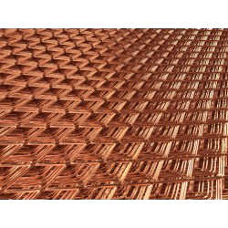
Place the ground wire in the rigid heat shrink tube and connect the flexible and rigid tube with the connector. The other end of the ground wire should be routed into the electrical panel behind the terminal block. The rigid tube can then be inserted into the collars. You just have to clip them to keep the tube in place.

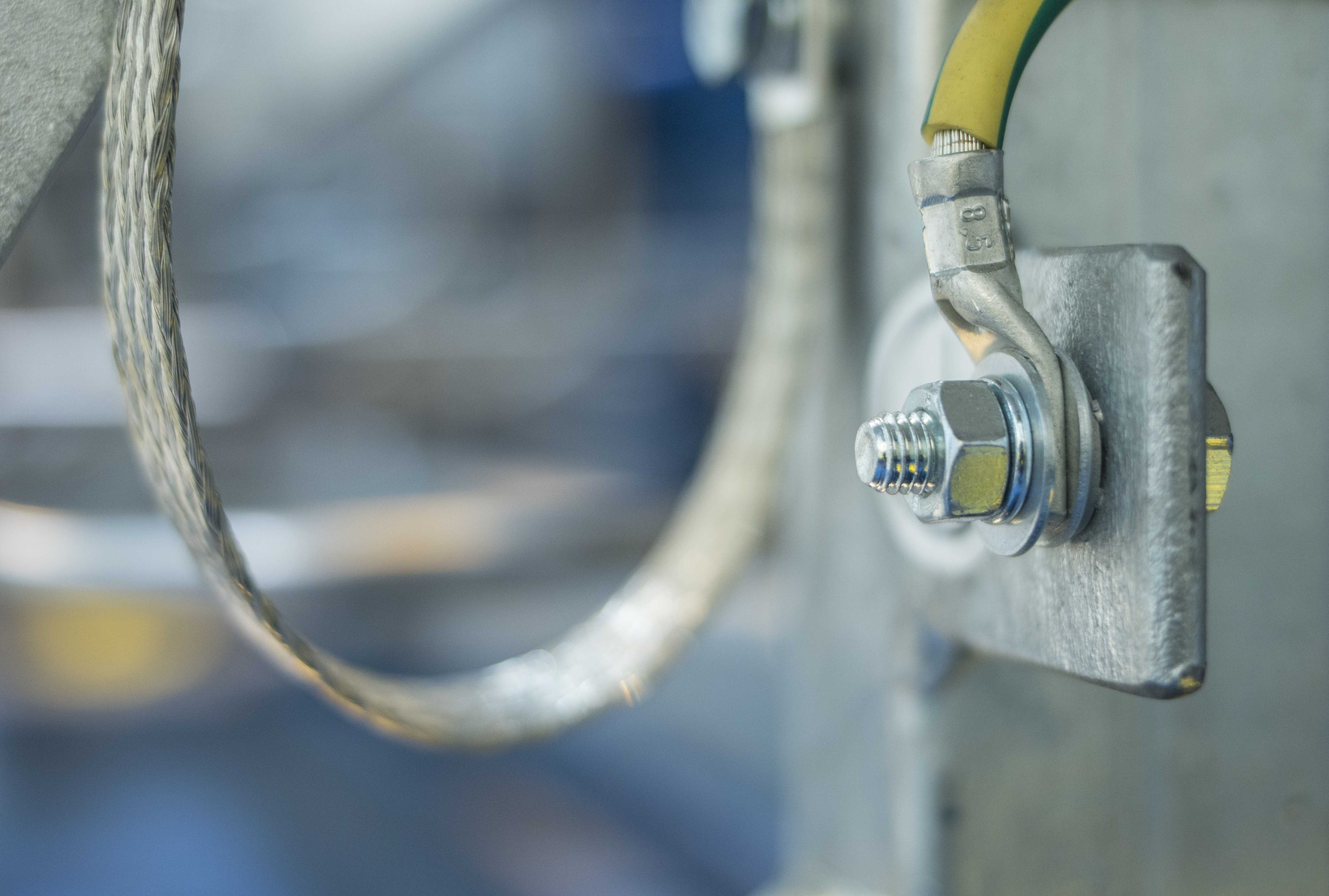
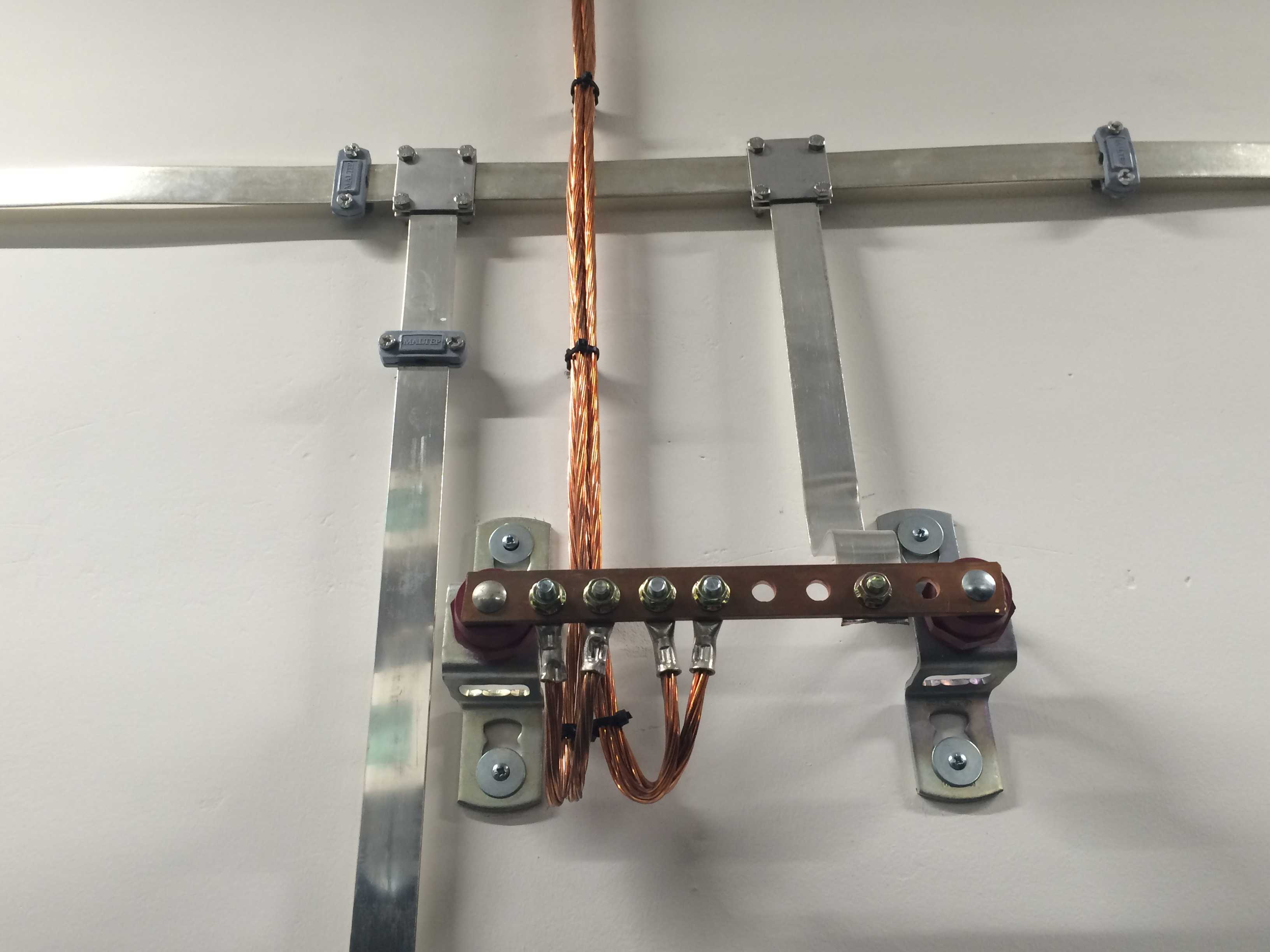
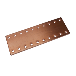
At the panel, cut the protruding wire and strip its end. Then unscrew one of the earthing terminal block fasteners located at the bottom of the electrical panel. Insert the wire into the earthing terminal block and screw the bracket back on. You can now close the panel.

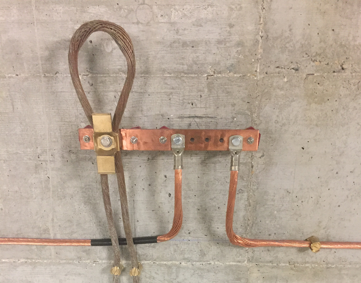
The earthing is now complete.

Attention :

Water, heating and gas lines should never be used as an earthing point.

MALTEP Earthing materials

Find all the earthing and grounding material at Maltep!

close

Wishlist