Our Businesses
THE LIGHTNING PROTECTION
A lightning strike can have dramatic consequences for the safety of people, but also for the functioning of an industrial installation or an electrical network
Methods of Protection
Learn how to protect yourself
Discover the field of lightning protection
The human and material consequences related to the risk of a lightning strike can be disastrous when a building or a structure is not effectively protected. Beyond the risks of fire and explosion, the overvoltages generated by a lightning strike can generate deterioration, premature aging or malfunctioning of equipment, or even an interruption or loss of production.
There are several methods of protection against direct lightning strikes:
• A lightning rod is placed at the top of the building
• The energy flows to the ground along the down conductor
• A control and maintenance device is installed between the lightning conductor and the earth electrod
• A mesh of protective conductors is laid around the building to be protected
• The conductors are equipped with lightning air terminals on the parts located at the top of the building
• Each down conductor is connected to an earth electrod
Principle diagram
Discover the lightning protection system
Case of an installation with a lightning rod
Discover the different components of a protection system against direct lightning strikes. In the case of an installation with a lightning rod, the categories of components are the following:
Air terminal and holders
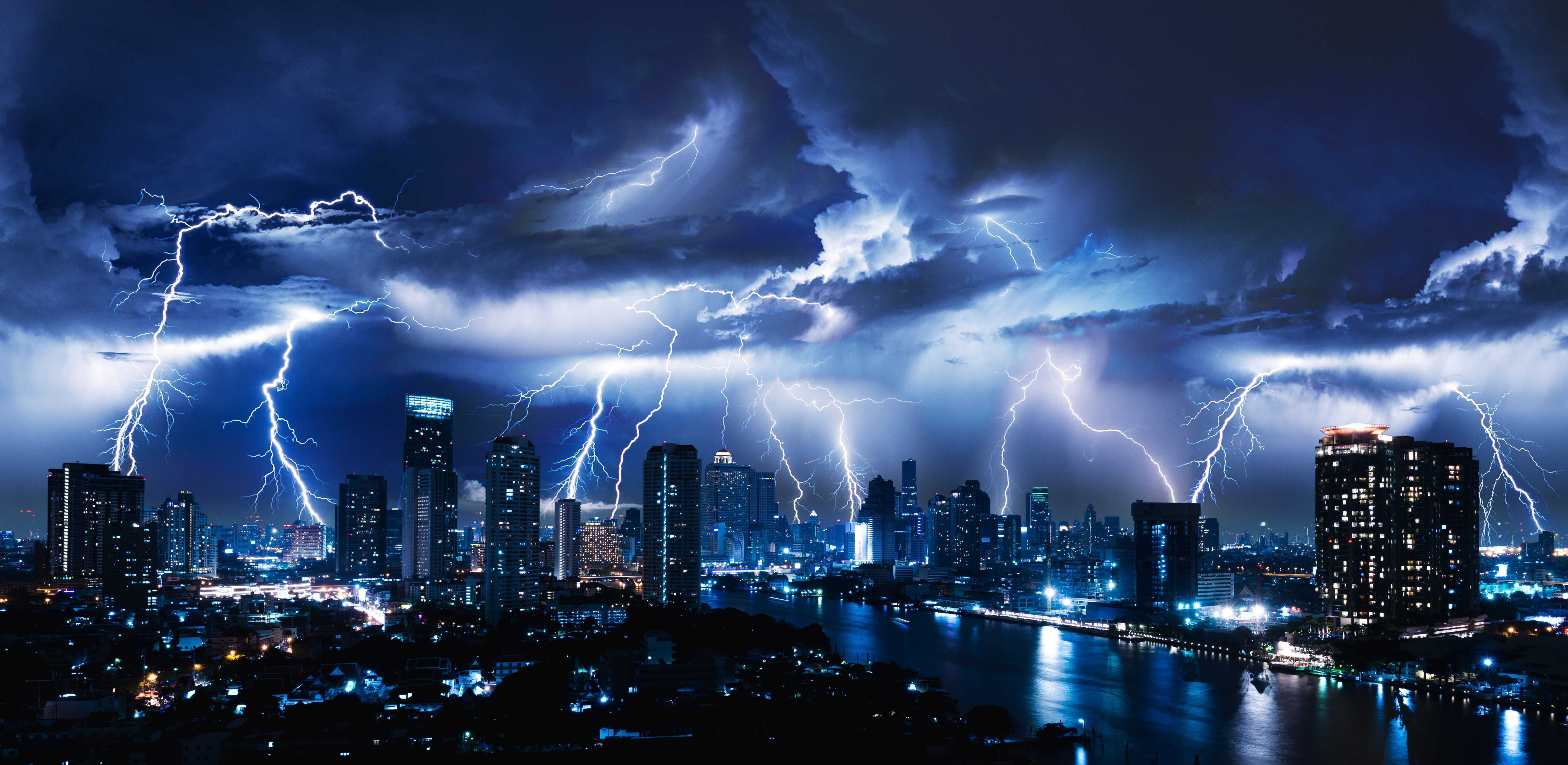
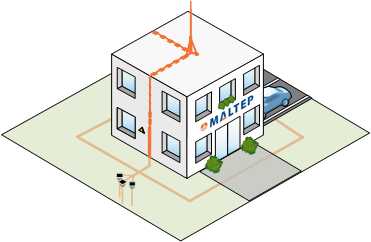
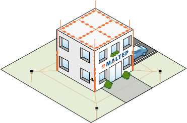
In a lightning protection system, the probability of a lightning current entering a structure or building is significantly reduced by the presence of a properly designed capture device. Capture devices typically consist of the following components:
- Lightning rods or by early streamer emission rods
- Masts (including separate masts)
- Air terminal in the case of a Faraday cage lightning protection system
The sizing, installation and positioning of lightning conductors, lightning rods and accessories are standardized both from the manufacturing point of view (IEC EN 62561-2, Grounding conductors and electrodes) and from the point of view of the installation of the device (IEC EN 62305). For all types of capture devices, only the actual physical dimensions of the metal capture devices should be used to determine the volume to be protected.
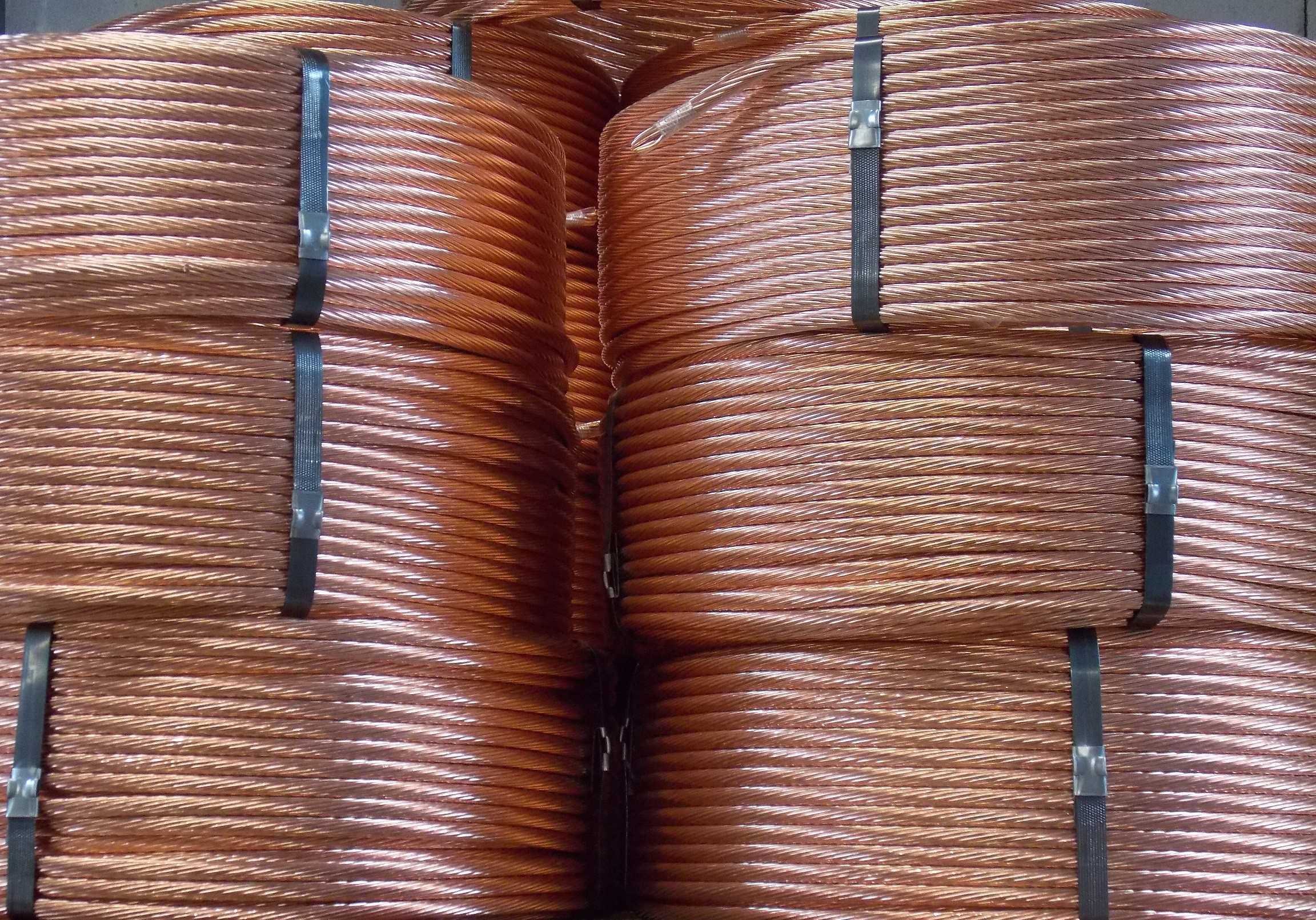
Down conductor
Selon la norme NF EN 62561-2, les conducteurs de descente doivent correspondre aux caractéristiques suivantes:
Matière: cuivre ou cuivre étamé
Ruban plein ≥ 50 mm² 2 mm d’épaisseur
Rond plein ≥ 50 mm² 8 mm de diamètre
Multibrins ≥ 50 mm² Brins de 1,7 mm de diamètre
Rond plein ≥ 176 mm² 15 mm de diamètre
Matière: Acier galvanisé à chaud
Ruban plein ≥ 50 mm² 2,5 mm d’épaisseur
Rond plein ≥ 50 mm² 8 mm de diamètre
Multibrins ≥ 50 mm² Brins de 1,7 mm de diamètre
Rond plein ≥ 176 mm² 15 mm de diamètre
Dans le cas d'une descente PDA, une structure métallique ayant une section suffisante peut assurer les descentes naturelles du PDA si les conditions de la norme sont remplies notamment la résistance de moins de 0,1 ohm. Il n’y a pas nécessité d’ajouter des descentes. Deux prises de terre de type A ou une de type B sont requises au minimum (une seule dans le cas de pylône métallique isolé de la structure).
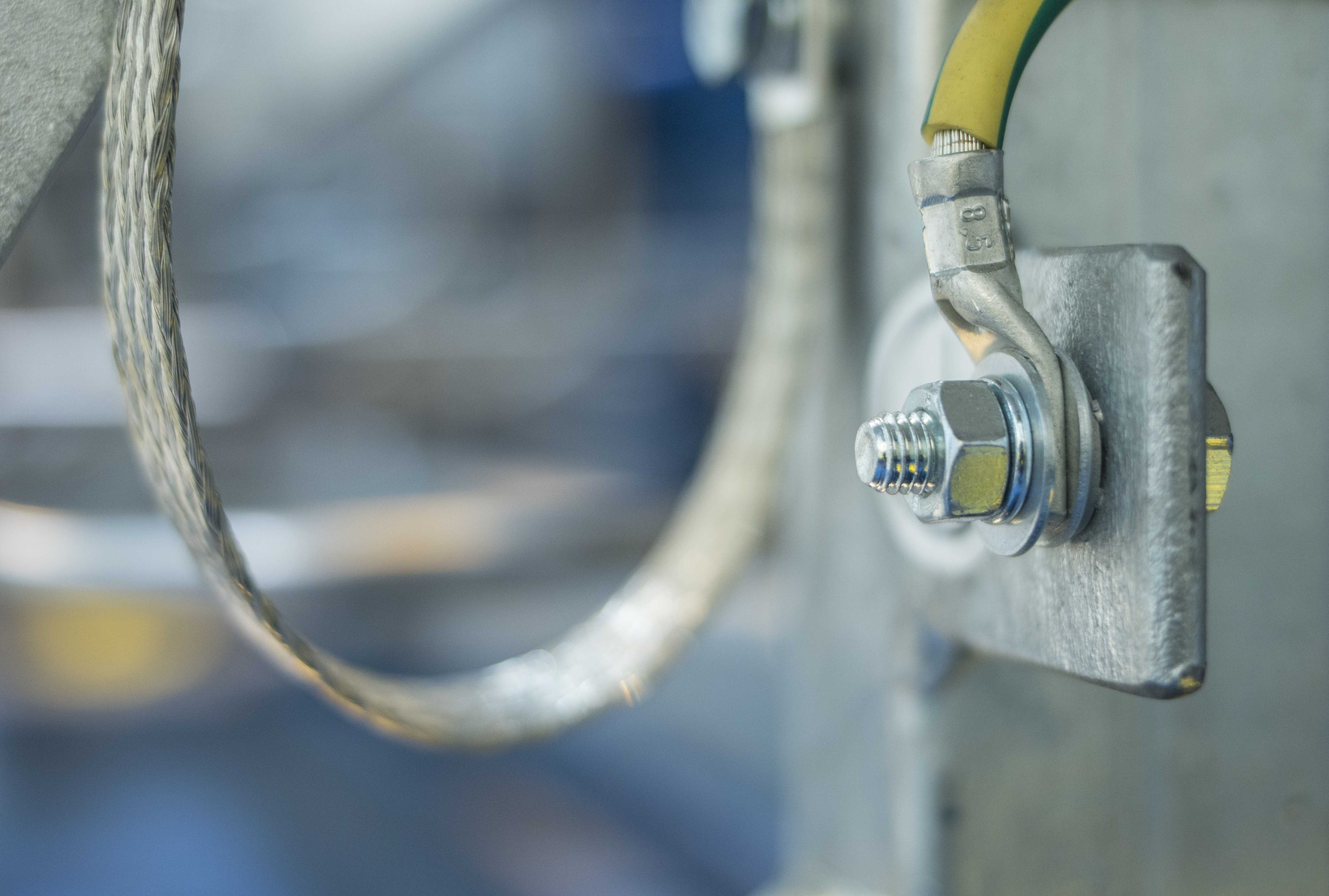
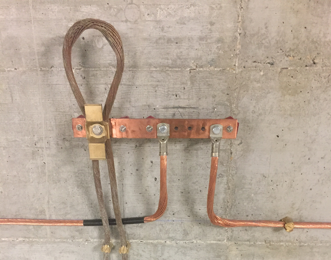
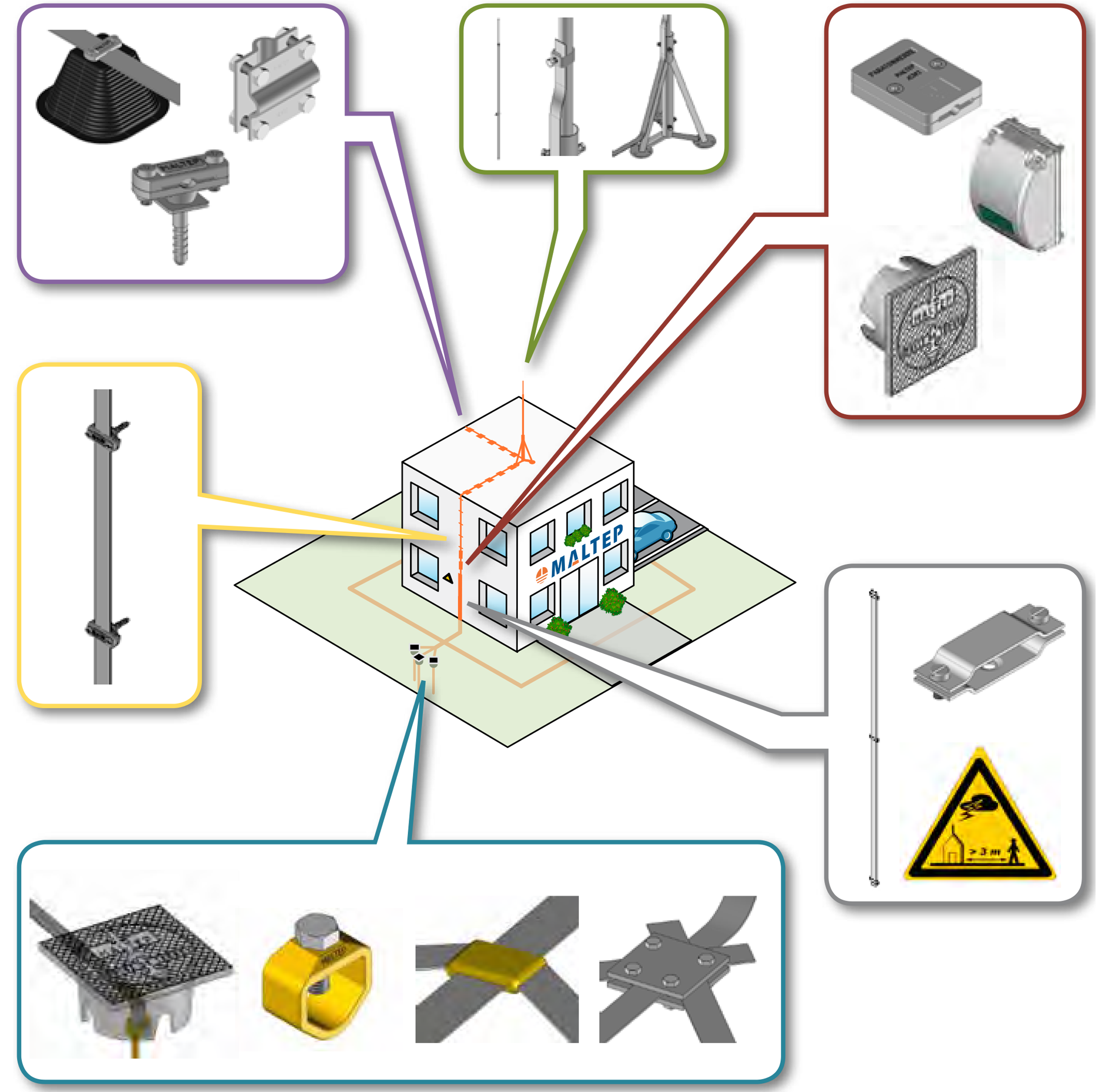
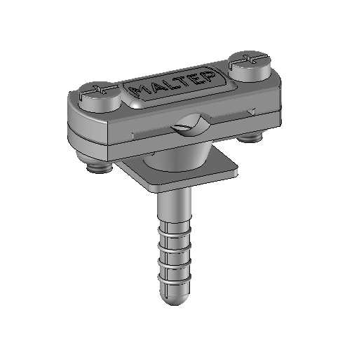
Conductor fasteners
Le conducteur de descente doit être fixé conformément à la norme NF EN 62561- 1 ou NF EN 62561-4 que ce soit le long du mur ou sur une connexion équipotentielle. Si une liaison équipotentielle est nécessaire entre le conducteur de descente et un équipement métallique à proximité (en cas de non-respect de la distance de séparation), la liaison équipotentielle sur l’équipement métallique peut être faite par rivetage.
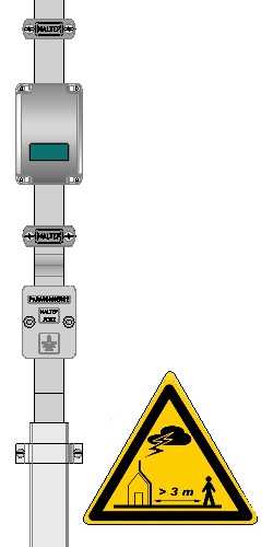
Protection and signalling
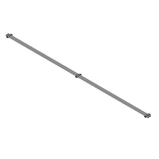
Les fourreaux de protection permettent de protéger le conducteur de descente jusqu'à une hauteur de 2m, afin d'éviter que des chocs mécaniques extérieurs ne détériorent la descente de foudre.
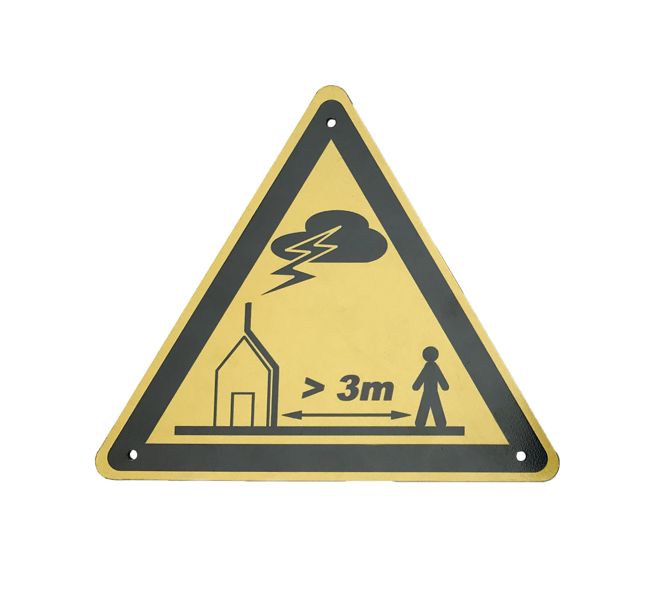
Les panneaux de signalisation sont obligatoires près de toute descente pouvant être approchée par du public afin de prévenir le risque humain.
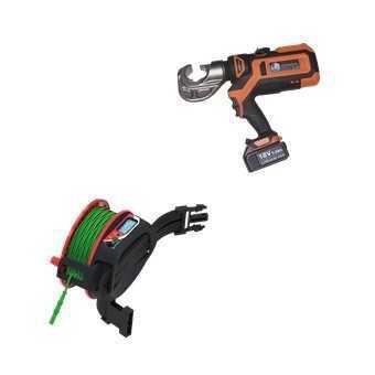
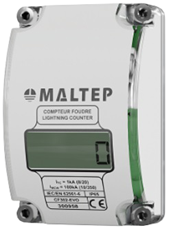
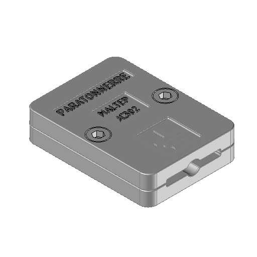
Control and maintenance
Les éléments de contrôle placés le long d'une descente de foudre doivent répondre à différentes versions de la norme NF EN 62561:
- Compteur de coups de foudre: NF EN 62561-6 - Exigences pour les compteurs de coups de foudre (LSC)
- Regard de visite: NF EN 62561-5 - Exigences pour les regards de visite et les joints d'étanchéité des électrodes de terre
- Joint de contrôle: NF EN 62561-1 - Exigences pour les composants de connexion
Ces éléments permettent de vérifier l'état et le bon fonctionnement du circuit de descente.
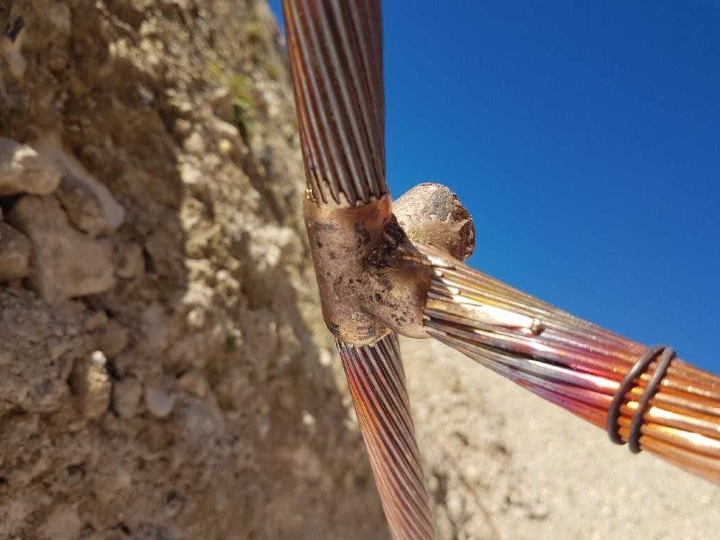
Earth electrode
L'électrode de terre doit permettre la dispersion du courant de descente dans le sol. Pour ce faire il doit réunir les conditions qui permettront à la résistance ohmique au niveau du joint de contrôle d'atteindre le niveau souhaité(100 Ohm selon la norme NF C15-100).
Les électrodes réalisées par fonçage de piquets de terre doivent de plus atteindre une profondeur minimale de 2m.
Detail of the installation
Support pour conducteur
Accédez à notre Catégorie de fixations pour fixations pour conducteur de descente
Compteur Foudre
Accédez à notre Catégorie contrôle et maintenance pour compteur foudre
Joint de contrôle
Accédez à notre Catégorie contrôle et maintenance pour joint de contrôle
Fourreau de protection
Accédez à notre Catégorie protection et signalisation pour fourreau de protection
Platine de signalisation
Accédez à notre Catégorie Protection et signalisation pour platines de signalisation
Products range
Discover the MALTEP lightning range
A complete range for your installation work
MALTEP offers a complete range of solutions for direct protection against lightning strikes
Flat and tape conductors
Round conductors
Stainless steel earth rods
Earth rod to tape clamps
U bolt earth rod clamp
5/8''Earth rod clamp
3/4''Earth rod clamp
Connecting head for earth rods
Wall offset bracket
Wall offset cross clamp
Mast brackets
Mast clamp
Lightning rods
Lightning rod extension masts
Clamp for lightning rod
Lightning rod base
Free standing air terminal support
Lightning air terminal
Stainless steel straight angle plate
Stainless steel plate
Normative background
Some standards to keep in mind
IEC EN 62305 : Protection against lightning
This standard specifies the rules for the installation of a lightning protection system and directly concerns MALTEPcustomers.
The standard IEC EN 62305 specifies the requirements for the protection of a structure against physical damage by a lightning protection system (LPS); and for the protection against injury to living beings due to touch and step voltages in the vicinity of a LPS. This standard is applicable :
- To the design, installation, inspection and maintenance of an LPS of structures, without limitation of their height
- To the implementation of measures for the protection against injuries of living beings due to contact and step voltages
IEC EN 62561 : Lightning Protection System Components
This standard specifies the requirements and tests to be applied for the production of lightning protection equipment. Therefore, it concerns manufacturers such as MALTEP. This standard consists of the following parts:
This part of IEC EN 62561-1 standard specifies the requirements and tests to be applied to metallic connecting components that are part of a lightning protection system.
Typical components include connectors, equipotential bonding components, branch components, expansion pieces, and control joints.
This part of IEC EN 62561-2 standard specifies requirements and tests for:
• Metallic conductors, other than "natural" conductors, that are part of the capture device and down conductors
• Metallic grounding electrodes that are part of the grounding system
• In the case of a PDA descent, two type A or one type B earthing points
are required (only one in the case of a metal tower isolated from the structure).
structure)
Type A: 3 crow's foot/line/triangle earthing rods
Type B: Conductor loop surrounding the structure at a minimum depth of 50cm
This part of IEC 62561-3 standard specifies the requirements for mast spark gaps.
- IIMP > Kc I with Kc I being the lightning current flowing in the appropriate part of the outdoor SPF
- The assigned shock voltage URIMP lower than the shock resistance level of the insulation between the elements.
The tests and trials are to be carried out in accordance with the EN 50164-3 standard
This part of IEC EN 62561-4 standard specifies the requirements and tests for metallic and non-metallic conductor supports that are used with air terminals, down conductors and earth terminals.
This standard does not address the mounting of supports to building structures, membranes, gravel roofs due to the many modern construction solutions.
This part of IEC EN 62561-5 standard specifies requirements and tests for:
• Grounding electrode inspection pits (inspection pits)
• Grounding electrode seals
This part of IEC EN 62561-6 standard specifies the requirements and tests for devices intended to count the number of lightning strikes passing through a conductor.
This conductor may be part of a lightning protection system (LPS) or connected to a lightning arrester installation (or other conductors that are not intended to conduct a significant portion of lightning currents).